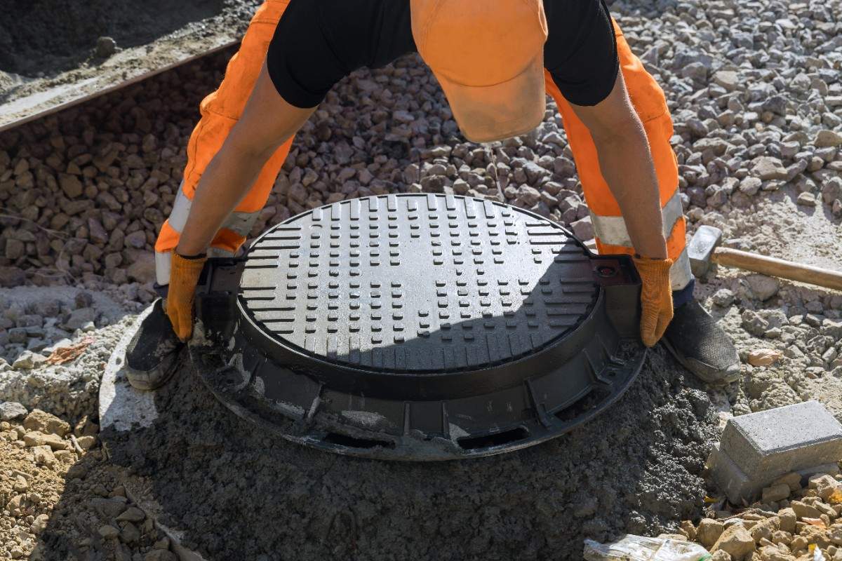
GIS (Geographic Information System) in utility asset management is the spatial data layer that anchors every infrastructure asset to its physical location, material attributes, and condition history. Without GIS, CMMS work orders are scheduled by asset record but cannot be mapped to geographic patterns, capital plans cannot account for spatial clustering of failing infrastructure, and field crews cannot navigate efficiently between job sites. The SMART360 asset management platform integrates GIS asset inventory with work order management and condition data to provide the spatial foundation that proactive asset management programs require.
Most water and gas utilities have some form of GIS, but many use it primarily as a mapping tool rather than an operational data layer. A pipe network map or a fire hydrant inventory is useful for planning purposes, but it does not produce the work order triggers, condition analysis, or capital prioritization inputs that asset management programs require.
GIS becomes operationally valuable in asset management when it serves three functions simultaneously: it stores asset attribute data (material, installation date, diameter, condition rating) alongside location data; it connects to the work order system so that maintenance events are spatially associated with the assets they address; and it provides the geographic analysis layer that surfaces patterns invisible in tabular asset records.
A utility with 50,000+ metered service connections that relies on GIS only for maps is leaving its most valuable data capability unused. The spatial relationships between aging mains, high-failure pressure zones, and active service connections are only visible when the CMMS data and the GIS data are combined.
A GIS asset inventory does more than record where assets are located. When built correctly, it supports five capabilities that non-spatial asset records cannot:
Does your utility have a complete, accurate GIS asset inventory, or are some asset classes tracked in spreadsheets, paper records, or disconnected CMMS databases without spatial association?
| Capability | Without GIS | With GIS Integration |
|---|---|---|
| Failure pattern identification | Visible only as frequency counts by asset class | Visible as geographic clusters by segment, zone, and soil type |
| Maintenance routing | Dispatched by address or crew familiarity | Optimized geographically by work order proximity and sequence |
| Capital project batching | Projects planned individually by failure event | Adjacent failing segments identified and batched in a single contract |
| Repair vs. replace analysis | Based on age and repair frequency alone | Augmented with spatial failure density and network interdependency |
| Regulatory compliance mapping | Manual cross-reference to permit documents | Automated spatial overlay flags assets within compliance zones |
| Field crew navigation | Street address or verbal directions | Digital map with turn-by-turn routing to asset location |
GIS does not function in isolation in a mature asset management program. Its operational value comes from integration with the other systems that generate asset condition data.
GIS and CMMS integration links every work order to the GIS asset record for the infrastructure asset addressed. This means that over time, the GIS inventory accumulates a maintenance history for each asset, including repair types, inspection findings, and replacement events. The CMMS generates work orders; GIS provides the spatial context that makes those work orders part of a pattern analysis rather than isolated events.
GIS and SCADA integration maps real-time telemetry readings to geographic asset locations. A pressure anomaly detected by a SCADA sensor is not just a reading; it is associated with a specific pipe segment and pressure zone in the GIS layer, which enables the asset management team to identify which infrastructure is most likely responsible and dispatch field crews to the correct location.
GIS and AMI integration maps interval meter reads to service connection locations. Zone-level demand analysis from AMI data is geographically associated with the distribution main segments serving each zone. Sustained demand anomalies in a specific geographic area trigger spatial investigation of the mains serving that zone, which can identify deterioration before it produces a reportable main break.
For a detailed roadmap of how GIS integrates with CMMS, SCADA, and AMI across the four maturity stages of digital asset management, utility asset management digital transformation covers the integration path and the sequencing of systems investment.
Proactive maintenance programs are driven by condition data, not calendar intervals. GIS contributes to proactive maintenance in two ways that non-spatial asset records cannot replicate.
First, GIS enables the identification of geographic maintenance zones where inspection frequency should be elevated. Pressure zones with a history of high repair frequency, soil conditions associated with accelerated corrosion, or pipe material types with known failure modes at specific ages are identified through spatial analysis of the GIS and CMMS data combined. Inspection cycles for these zones are set at higher frequency than the utility-wide default.
Second, GIS-based routing makes proactive inspection programs operationally practical. A utility conducting condition assessments on all mains over 40 years old in cast iron or unlined ductile iron must sequence those inspections efficiently to complete the assessment program within a reasonable timeframe. GIS routing tools batch inspection stops geographically so that field crews cover high-priority areas systematically rather than responding to individual dispatch requests.
For a full analysis of what reactive programs cost and the mechanism by which proactive maintenance reduces emergency repair frequency, proactive vs. reactive maintenance at water utilities covers the cost differential and the operational transition.
AI-driven failure prediction models trained on CMMS work order data produce risk scores for individual assets. When those risk scores are mapped to GIS records, the analysis gains a spatial dimension that the tabular model cannot provide on its own.
A pipe segment with a high individual failure probability score may be in a zone where three adjacent segments also score high. GIS analysis of the combined spatial risk reveals a replacement project candidate that addresses all four segments in a single excavation rather than four sequential emergency responses. Without GIS, the tabular model sees four individual asset scores; with GIS, the analysis surfaces a geographic concentration that changes the capital planning recommendation.
GIS also enables correlation analysis between asset failure patterns and environmental variables. Soil corrosivity data, road load data from traffic counts, and frost depth data can be overlaid on the asset network in GIS to identify which environmental factors contribute most strongly to failure rates in specific zones. This analysis improves failure prediction model accuracy by adding geographic context that the CMMS data alone does not capture.
For a detailed treatment of how AI applies to utility asset condition data and what the implementation steps involve, AI in utility asset management covers the data inputs, the anomaly detection approach, and the asset classes where AI delivers the fastest return.
The repair vs. replace framework for individual assets produces a per-asset recommendation based on condition score, repair frequency, and replacement cost ratio. GIS adds a spatial dimension that changes some of those recommendations.
An individual pipe segment that scores just below the replacement threshold on a per-asset basis may score above the threshold when its geographic context is considered. If the segment is in a zone with three adjacent segments already scheduled for replacement, replacing it in the same project eliminates the mobilization, excavation, and surface restoration costs that would apply if it were addressed as a standalone project in the future. The GIS analysis reveals this opportunity; the per-asset framework alone does not.
Similarly, a segment that appears low-priority based on age and repair frequency may be in a pressure zone where GIS analysis reveals high failure density among peer segments of the same material and vintage. The spatial pattern provides evidence of accelerated deterioration in that zone that is not visible in the individual asset record.
For a complete framework for making repair vs. replace decisions using condition data, including the five-step scoring process, water utility asset repair vs. replace decision framework covers the criteria and how spatial inputs from GIS augment the per-asset analysis.
Does your utility's GIS inventory include installation dates, material types, and condition scores for all asset classes, or are fields missing for older infrastructure that predate digital records?
SMART360 supports GIS integration with CMMS work order management, connecting spatial asset records to the condition data and maintenance history that drive proactive program decisions. For utilities evaluating the full ROI of the asset management software investment, including how GIS-enabled capital project clustering and repair vs. replace optimization contribute to the cost savings case, utility asset management software ROI covers the measurement methodology.
GIS in utility asset management is the spatial data layer that associates each infrastructure asset with its physical location, attribute data, and maintenance history. It enables utilities to analyze failure patterns geographically, optimize maintenance routing, batch capital projects for adjacent infrastructure, and overlay regulatory compliance boundaries on the asset network. GIS becomes most valuable when it is integrated with the CMMS, SCADA, and AMI systems that generate the asset condition and work order data that the spatial analysis layer requires.
Most utilities have GIS in some form, but many use it as a mapping tool rather than an operational data layer. The gap is typically one of three types: the GIS inventory is incomplete (some asset classes are not in the system, or attribute fields are missing for older infrastructure); the GIS is not connected to the CMMS (work orders are not spatially associated with asset records); or the GIS data is not being analyzed for failure patterns and capital planning inputs. The operational value of GIS is realized only when the spatial data connects to the systems that generate condition and maintenance history.
For a utility starting from partial GIS coverage, a complete inventory for the highest-risk asset classes typically takes 12 to 24 months of field verification work. The timeline depends on the size of the network, the availability of historical records, and the field crew capacity allocated to the verification program. Utilities that prioritize high-consequence assets first can begin using GIS for capital planning inputs within the first six months while verification of lower-risk asset classes continues.
A GIS asset record needs at minimum: asset type and unique identifier, spatial location (coordinates or as-built survey), installation date, material and diameter, current condition score, and date of last inspection. For pipe segments, operating pressure zone and soil classification are also valuable. Missing installation dates are the most common gap in older utility inventories and the most damaging to remaining useful life estimates, since lifecycle calculations depend on knowing when the asset entered service.
Bynry Inc.
8 The Green STE.R,
Dover, Kent,
Delaware 19901
+1 732-630-0285
Bynry Inc.
Serene Tower, Pakharbaug
Pune, Maharashtra 411021
+91 93252-51217